Fundamentals
The foundations of this work begin with a theoretical section. This section first describes an Evil Maid Attack and then presents concepts for mitigating such an attack. The TPM, Intel Trusted Execution Technology (Intel TXT), and AMD Secure Virtual Machine (SVM) are essential hardware components for implementing countermeasures. The software leverages these hardware features to establish a secure boot environment. This work explains each relevant component, from the lower levels where the firmware resides to the higher levels where the operating system runs.
A basic understanding of asymmetric cryptography is assumed. Knowledge in low-level programming with assembler and familiarity with the x86-64 processor platform are also helpful.
Evil Maid Attack
Attacks can be classified as either opportunistic or targeted. In opportunistic attacks, the attacker is not familiar with the victim. They simply exploit opportunities that arise by chance. The following example illustrates an opportunistic attack: after paying, a customer forgets their laptop in a café. An attacker who is also in the café notices this and extracts confidential data from the system. In contrast, a targeted attack involves minimizing the number of factors dependent on chance. The attacker gathers as much information about the victim as possible and selects the most promising attack vector based on this knowledge. The following example illustrates a targeted attack: Malory seeks information from Bob’s laptop. She knows that Bob takes his laptop to a café every Friday, goes to the restroom at least once, and does not lock his laptop during this time. Malory plans to copy a confidential file from Bob’s laptop within this window.
A successful Evil Maid Attack (EMA) requires detailed information about the target system. Additionally, either repeated physical access or extended access over time is necessary. Consequently, EMAs are considered targeted attacks.
Full Disk Encryption (FDE) protects the confidentiality of data in a system’s powered-off state against attackers with physical access. However, FDE provides no protection against malware that is executed after authentication to the system has occurred. This also applies to unlocked systems that an attacker can physically access [18]. If most of the attack vectors are impossible, an attacker might consider using an EMA to gain access to encrypted and confidential data.
An Evil Maid Attack (EMA) may require either one-time or repeated physical access to the hardware. With single access, an image of the hard drive is created, and the bootloader is replaced with a manipulated version that transmits the password, for example, over a connected network. If repeated physical access is possible, it may be sufficient to store the password on the hard drive. Generally, an attack with multiple access opportunities is easier to execute. For a one-time access attack to be feasible, the key material must be stored on the hard drive rather than on a USB stick or in a TPM. Additionally, a significant amount of time is required to create a complete copy of the hard drive without the victim noticing the attack.
Tampering can involve either software or hardware components. Examples of hardware manipulation include attaching a USB keylogger [19], exfiltrating data via a USB-based Man-in-the-Middle attack, or even creating a complete duplicate of the target system. Software manipulation, on the other hand, includes not only programs stored on the system’s hard drive but also firmware held in the flash memory of integrated circuits (ICs). Additionally, modifications to data processed by these programs may also count as software tampering, especially if vulnerabilities like buffer overflows are used to inject code into them.
Thus, the definition of an EMA for this work can be formulated as follows: In an EMA, an attacker with single or repeated physical access manipulates the hardware or software components of a target system protected by FDE to obtain the authentication token of a specifically chosen victim. The victim must successfully authenticate on the compromised system at least once.
An attack is not necessarily a security vulnerability. Whether an EMA is considered a security vulnerability is determined by the security policy. For laptops used exclusively within a corporate environment, it may be deemed acceptable not to categorize this attack vector as a vulnerability. If an EMA is considered a security vulnerability, then the security policy must define the security objectives that an EMA would compromise. Confidentiality, Integrity, and Availability (CIA) are the established security goals in Information Technology (IT). When software or hardware is altered, integrity is compromised, and in the case of a successful attack, confidentiality may also be affected. If an EMA is classified as a security vulnerability, security measures should be implemented to protect against this type of attack. This master’s thesis aims to develop precisely such a security measure for OpenBSD, enabling detection of software manipulations that remain unencrypted even with active FDE, before a password entry is required. Detecting hardware or firmware manipulations is initially out of scope and could be addressed in future research.
Countermeasures
Now that an EMA has been precisely defined, this chapter addresses theoretical countermeasures. Established solutions are based on two distinct theoretical approaches. Secure Boot detects software manipulation through cryptographic signatures, while Qubes-AEM measures and logs the software being executed. Starting with signatures, both approaches are examined and evaluated in detail below.
Signatures
Cryptographic signatures typically function through a combination of cryptographically secure hash algorithms and asymmetric encryption methods, such as Rivest–Shamir–Adleman (RSA). An executable file is reduced, for example, to a 20-byte value using SHA-1. This value is then encrypted with the private portion of the key material and appended to the file as a signature. Third parties can generate the hash value independently and compare it to the decrypted signature. If both match, it can be concluded that no tampering has occurred. [23]
Secure Boot is a process defined in the UEFI specification that validates the signatures of software executed by the firmware. When Secure Boot is enabled, any software in the boot chain without a valid signature will cause the boot process to fail. The process begins with a Root of Trust and establishes a chain of trust, where each program verifies the signature of the next. Computers with the “Compatible with Windows” logo are required to include Microsoft’s digital keys and ship with Secure Boot enabled by default. Alternative operating systems, such as Fedora and Ubuntu, are also compatible with Secure Boot. If an operating system or boot software lacks a valid signature, users can self-sign it and register the corresponding key in the (UEFI). [28]
Secure Boot represents a significant improvement over systems that lack any security mechanisms. However, it is not sufficient for ensuring a fully secure boot process, as it does not account for the data used by the programs. Buffer overflow vulnerabilities, for instance, can allow attackers to alter the control flow and execute malicious code. Signature-based approaches are unable to detect such exploits, leaving this as a critical security gap.
The measurement of components, which will be explained in more detail in the next section, enables the detection of modifications to programs and the data they use.
Measurements
Measurement refers to the process of recording both executed software and the data it processes. Instead of storing full copies of the software, the protocol relies cryptographically secure hash function to conserve storage. The integrity and reliability of these hash values are directly tied to the cryptographic strength of the hash function used. Assuming the use of a secure hash function, it becomes computationally infeasible to generate a malicious copy that produces an identical hash. The measurement log can be queried by software to assess whether the system state has deviated from a previously known and verified configuration.
To address the trust evaluation question in practice, it is essential to carefully determine which software measurements should be considered for this purpose. If too many measurements are included, the system could not be trusted after each boot, as certain data—such as the OptionROMs stored in the Basic Input Output System (BIOS)—can vary from one boot to the next [60]. Striking an appropriate balance between security and practical usability is therefore crucial. This involves selecting measurements that are critical to the integrity of the system while minimizing variability that could undermine trust without reason.
As with cryptographic signatures, measurement-based approaches also require a Root of Trust, which must itself be inherently trustworthy. In the TPM specification, this is referred to as the Root of Trust for Measurement (RTM). The RTM’s sole responsibility is to measure the next program in the execution chain. Beyond this task, it does not perform any additional functions, ensuring a clear and focused role in establishing the trustworthiness of subsequent components.
In addition to the Root of Trust, the method by which the measurement log is maintained is a critical consideration. Foremost, it must be ensured that the log cannot be modified retroactively. This requirement excludes most types of storage available in modern systems. On the amd64 platform, for instance, only certain processor registers that can be written to once per boot cycle or Read-Only Memory meet this criterion. However, these options are insufficient for broader use, necessitating dedicated hardware that provides tamper-resistant storage.
Equally important is ensuring the integrity of the log and that the results of any log queries cannot be falsified. Addressing these challenges is the focus of the Trusted Computing Group (TCG), which developed the Trusted Platform Module (TPM) as a solution. The TPM, along with its features and functionality, is introduced in the following chapter on foundational concepts.
Hardware
This chapter delves into the hardware components essential for understanding this work, covering the fundamentals of the Trusted Platform Module (TPM), various approaches to the Root of Trust for Measurement (RTM), and relevant processor extensions. The TPM is an independent System on a Chip (SoC), designed to provide secure cryptographic operations and measurement capabilities. In contrast, Intel Trusted Execution Technology (Intel TXT) and AMD Secure Virtual Machine (SVM) represent extensions of the i386 and amd64 Instruction Set Architectures (ISA), respectively, and are utilized to implement a Dynamic Root of Trust for Measurement (DRTM).
Trusted Platform Module
A secure implementation of measured software is not possible without hardware, a fact recognized by the Trusted Computing Group (TCG), which led to the development of the TPM specification. This thesis utilizes the Trusted Platform Module (TPM) described within the specification for both measuring software components and encrypting/decrypting secrets.
The Trusted Platform Module (TPM) refers not only to the specification but also to the corresponding System on a Chip (SoC). This passive cryptographic co-processor provides several functions designed to enhance the security of systems. The first widely adopted version, TPM 1.1b, was released in 2003. This was followed by version 1.2 in 2005, which introduced better protection against dictionary attacks, a standardized API/SoC pin layout, and Direct Anonymous Attestation (DAA). In 2014, the latest version, TPM 2.0, was released, offering additional enhancements, including greater flexibility in the selection of supported algorithms [29] (chap. 1) . For the purposes of this thesis, only version 1.2 will be used to minimize the number of variables involved.
TPM-Owner und Storage Root Key
When the TPM is in its factory state, a TPM Owner must be set in order to utilize its full functionality. To do this, a secret is transferred into the TPM, which will later serve to authenticate the owner. For the TPM, the secret is a 20-byte array. Users are free to choose how the content of this secret is generated [30] (chap. 7).
To keep the manufacturing costs of a TPM as low as possible, the specification requires only a minimal amount of internal non-volatile memory. To still enable the creation of a variety of different keys, whose private parts are never accessible outside the TPM, a hierarchy is established, with the Storage Root Key (SRK) at the root. During the initialization of the TPM, this key is set to a random value. Similar to the TPM Owner, a secret must also be established for the SRK. This secret is referred to as the SRK password.
The tpm-tools allow the execution of many TPM commands from the command line. On
Fedora, they can be installed using the command sudo dnf install tpm-tools.
After installation, it is possible to set oneself as the owner of a TPM using
the command tpm_takeownership. For further details, the third section of the
TPM specification in Chapter 6.1 can be consulted, which provides a detailed
description of the parameters of the tpm_takeownership command.
Platform Control Registers
A Platform Control Register (PCR) is a 160-bit protected storage area within the TPM. In TPM 1.2, there are at least 16 PCRs, which can store an arbitrary number of integrity measurement values by chaining them through the extend operation [30] (chap. 4.4).
After a platform reset, the contents of the Platform Control Registers (PCRs)
are reset to zero and can subsequently only be modified through the extend
operation. Let H represent the cryptographic hash function SHA-1,
PCRi denote the content of the PCR register with index i, and E be
the SHA-1 value of the measured data. The extend operation is defined as
follows [30] (chap. 4.4):
In addition to these fundamental properties, the TPM PC Client Specification [34] also recommends which integrity measurement values should be stored in which PCRs. Table 1 shows the details.
PCR Index |
PCR Usage |
|---|---|
0 |
S-CRTM, BIOS, Host Platform Extensions, and Option ROMs |
1 |
Host Platform Configuration |
2 |
Option ROM Code |
3 |
Option ROM Configuration and Data |
4 |
IPL Code (usually the MBR) and Boot Attempts |
5 |
IPL Code Configuration and Data (for use by the IPL Code) |
6 |
State Transitions and Wake Events |
7 |
Host Platform Manufacturer Specific |
8-1 |
Defined for use by the Static OS |
16 |
Debug |
23 |
Application Support |
PCR-08 to PCR-15 are reserved for use by the operating system.
Therefore, if OpenBSD wishes to measure its own software components, these PCRs
are available for this purpose.
The values in the PCRs can not only be queried but also set as conditions for decrypting data. This type of encryption, referred to by the TCG as Sealing and Unsealing, is explained in the following section.
Sealing and Unsealing
Sealing refers to the process of encrypting data using a TPM. The resulting
ciphertext can only be decrypted by the same TPM because the specified key must
be non-migratable. In other words, the private part of the key, by definition,
never leaves the TPM [32] (chap. 10.1). In addition to the key handle, PCR
indexes can also be specified. This means that the TPM will only decrypt the
data if the contents of the PCRs match the values they had when the data was
originally sealed. The following information is required when invoking the
tpm_seal command:
Key: The Key Handle pointing to a non-migratable key. According to the specification, Key Handles are 32-bit integers, and integral keys such as the Storage Root Key (SRK) have a fixed value. For the SRK, this value is
0x40000000.KeyAuth: When using a key, the TPM requires proof that the invoking party is authorized to do so. Authorized individuals are those in possession of the shared secret associated with the key. This shared secret is a 20-byte array, which is not transmitted directly but instead used as a key in an HMAC (Hash-based Message Authentication Code) algorithm.
Data: The data to be encrypted, which can be up to 256 bytes in size. If the data exceeds this size, a symmetric key must be used as an intermediate step.
DataAuth: Authorization data that must be provided to prove knowledge when calling the tpm_unseal command. This data is encrypted and transmitted securely over the Low Pin Count (LPC) bus to ensure confidentiality.
PCR Indexes: The PCR indexes whose contents are tied to the decryption process, such as
PCR-01,PCR-02,PCR-03.
The result of the Seal operation is a data stream that contains all the
necessary information for the TPM to later decrypt the data. This includes the
contents of the PCR at the time of encryption. These and additional data must be
provided when executing tpm_unseal.
Key: The same as for
tpm_seal.KeyAuth: The same as for
tpm_seal.Data: The response form
tpm_seal.DataAuth: The same as for
tmp_seal.
Root of Trust for Measurement
The TPM is a passive component that does not directly influence which software runs on a system. To ensure that the executed software and the contents of the PCR are consistent, a Chain of Trust is employed, in so overcoming the limitation of not being in control.
Starting from a Root of Trust, or in the context of measurements, a Root of Trust for Measurement (RTM), each executed software component is measured by its predecessor. The RTM is unique because it has no predecessor and is therefore implicitly trusted. Consequently, any manipulation of the RTM must be rendered impossible. In the TPM specification, the RTM is also referred to as the Core Root of Trust for Measurement (CRTM).
In a system employing a Static Root of Trust for Measurement (S-RTM), the CRTM must not only remain immutable but also execute as early as possible during platform initialization. The following excerpt from the specification defines the key properties of the S-CRTM:
The Static Core Root of Trust for Measurement (S-CRTM) MUST be an immutable portion of the Host Platform’s initialization code. See Section 1.2.2 (Immutable). [30] (chap. 3.3.1.2)
The entries in the PCR content table (Table 2.1) illustrate the Chain of Trust within a system utilizing a Static Root of Trust for Measurement (SRTM). Since the CRTM is implicitly trusted, it measures itself, the BIOS, the Host Platform Extensions, and the Embedded Option ROMs. The resulting measurement values are stored in PCR-00, PCR-01, PCR-02, and PCR-03, respectively.
The CRTM subsequently hands over control to the BIOS, which then measures the Initial Program Loader (IPL) code. In IBM XT2-compatible systems, this corresponds to the Master Boot Record (MBR). The MBR can return control to the BIOS if issues arise. If an additional IPL is available, PCR-04 is extended again, thereby capturing all boot attempts within its cumulative measurement.
The more programs that gain control of the system during startup, the higher the likelihood that the system’s trustworthiness will be compromised. This is because updates to individual components, even when made with no malicious intent, can alter the contents of the PCRs [38] (chap. 1.2).
Dynamic Root of Trust for Measurement (DRTM) provides a solution to this challenge. This approach allows for the initiation of a measured environment at any arbitrary point in time. To facilitate this, PCRs that can be reset were introduced. The reset operation is restricted to specific entities through different privilege levels, referred to in the TPM specification as Localities. Table 2 provides a detailed overview of which PCRs can be reset and the required Locality level for performing this operation.
PCR Index |
Alias |
pcrReset |
pcrResetLocal (4, 3, 2, 1, 0) |
pcrExtendLocal (4, 3 ,2, 1, 0) |
|---|---|---|---|---|
0 – 15 |
Static RTM |
0 |
0,0,0,0,0 |
1,1,1,1,1 |
16 |
Debug |
1 |
1,1,1,1,1 |
1,1,1,1,1 |
17 |
Locality 4 |
1 |
1,0,0,0,0 |
1,1,1,0,0 |
18 |
Locality 3 |
1 |
1,0,0,0,0 |
1,1,1,0,0 |
19 |
Locality 2 |
1 |
1,0,0,0,0 |
0,1,1,0,0 |
20 |
Locality 1 |
1 |
1,0,1,0,0 |
0,1,1,1,0 |
21 |
Dynamic OS Controlled |
1 |
0,0,1,0,0 |
0,0,1,0,0 |
22 |
Dynamic OS Controlled |
1 |
0,0,1,0,0 |
0,0,1,0,0 |
23 |
Application Specific |
1 |
1,1,1,1,1 |
1,1,1,1,1 |
It is the platform’s responsibility to ensure that Localities cannot be spoofed. Specifically, Locality 4 can only originate from the CPU itself, necessitating additional processor features. Both Advanced Micro Devices (AMD) and Intel provide extensions that enable DRTM in conjunction with a TPM. These extensions are briefly described in the following sections.
Intel Trusted Execution Technology
Intel Trusted Execution Technology (TXT) is Intel’s branding for a suite of technologies designed to enhance the security of existing computer systems. It outlines platform enhancements and building blocks essential for implementing Trusted Computing principles [38] (chap. 1).
As previously outlined, Intel TXT enables the initiation of a Chain of Trust with a dynamic origin. This approach offers the advantage of maintaining a shorter chain, reducing the number of components involved and thus minimizing the number of components required to be trustworthy.
The newly introduced processor instruction SENTER enables the launch of a Measured Launch Environment (MLE). This instruction first synchronizes all processor cores and then executes the Authenticated Code Module (ACM) on the Initiating Logical Processor (ILP), provided the ACM carries a valid signature from Intel. Prior to invoking the instruction, both the ACM and the MLE must be loaded into memory to ensure proper execution [38] (chap. 1.2.1).
The Authenticated Code Module (ACM) verifies the state of the Central Processing Unit (CPU). If the configuration is deemed satisfactory, it resets PCRs 17–23. Subsequently, the ACM measures itself and the Measured Launch Environment (MLE) into PCR-17, after which control of the system is handed over to the MLE [38] (chap. 1.1–1.9).
Fig. 1 illustrates how Intel utilizes the four localities defined in the TPM specification. When analyzed alongside Table 2.2, it becomes evident which combinations of software components and PCRs are authorized to perform either the Reset or Extend operations.
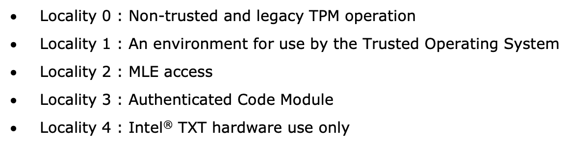
Fig. 1 TXT Localities
With Intel TXT and resettable PCRs, it is possible to launch an MLE at any desired point in time. For further details, refer to Intel’s Software Development Guide [38], the book A Practical Guide to TPM 2.0 [29] (chap. 22), or the book Intel Trusted Execution Technology for Server Platforms.
AMD Secure Virtual Machine
In addition to Intel, AMD also provides the capability to initiate a trusted environment at runtime through its Secure Virtual Machine technology. If supported by the CPU, this can be achieved by executing the SKINIT instruction.
The SKINIT instruction requires a single parameter in the eax register, which is the address of a Secure Loader Block (SLB). This SLB is AMD’s term for the memory region containing the Secure Loader Image (SLI). The SLI includes both the code and initialized data for the Secure Loader (SL) program. The SL is responsible for initializing the Secure Virtual Machine (SVM) hardware mechanisms and transferring control to the next software component, referred to by AMD as the Security Kernel. In practical applications, this Security Kernel is often a Virtual Machine Monitor (VMM) [52] (chap. 2.4) [36] (chap. 15.27).
Before the first instruction of the Secure Loader (SL) program is executed, the SKINIT instruction initializes the processor to a well-defined state. In this state, modifications to the Secure Loader Image (SLI) are prevented. Additionally, interrupts are disabled, ensuring that no previously executed code can regain control of the system. This guarantees a secure and isolated execution environment for the SL program [36] (chap. 15.27).
Once all hardware protection mechanisms are activated, the CPU sends a signal to
reset the dynamic PCRs to the TPM. Following this, the processor transmits the
Secure Loader Image (SLI) to the TPM, which computes a cryptographic hash of the
received data and extends PCR-17 with the resulting value. This coordinated
interaction between hardware and software establishes a Root of Trust that
serves as the foundation for further extensions within the trust chain.
The book Trust Extension as a Mechanism for Secure Code Execution on Commodity Computers [52] provides a highly accessible explanation of AMD SVM and Intel TXT in Chapter 2.4. For more detailed information on AMD’s technology, the second volume of the AMD64 Architecture Manual [36], specifically Section 15.2, offers an in-depth exploration.
With this, the foundational knowledge regarding hardware is complete. The sections on Intel TXT and AMD SVM have been kept intentionally brief, as neither technology is utilized in the implementation. The following chapter will focus on the software components, spanning from firmware to the operating system, that are executed during the startup of OpenBSD on an IBM XT-compatible system.
Firmware
After a platform reset of an i386 or amd64 CPU, the processor enters real mode
with only a single core active. The Extended Instruction Pointer (EIP) register
is set to the address FFFF:FFF0, known as the reset vector [35] (chap.
8.4.3). At this address resides the system firmware, which, in the case of the
test system used in this work, implements UEFI.
The responsibilities of firmware include performing the Power-On Self Test (POST), during which the installed hardware is checked for functionality, and booting an operating system through chainloading. Essential hardware components, such as the keyboard, display, and storage devices, are initialized by the firmware and made operational. These components are then exposed to subsequent software via an Application Programming Interface (API) [39] (chap. 1). Both the unofficial BIOS standard and the official UEFI standard define such APIs, which will be introduced in the following sections.
Unified Extensible Firmware Interface
On January 31, 2006, the first version of the UEFI specification was published. Its goal, as well as that of its predecessor, the Extensible Firmware Interface (EFI) developed by Intel, was to reduce platform dependency in firmware [40]. Leveraging the opportunity for a fresh start, numerous additional improvements were introduced alongside this primary objective. These enhancements include support for GUID Partition Table (GPT), 64-bit firmware code, and security features such as Secure Boot.
Although UEFI is already widely adopted and is poised to play an even more significant role in firmware in the future, this work opted to enable the Compatibility Support Module (CSM). The CSM emulates a legacy BIOS, allowing for the traditional boot process of an operating system [41]. This decision was made for the following reasons:
Existing software solutions such as TrustedGRUB2 or the AEM module in QubesOS are designed to work with legacy BIOS. Using legacy BIOS is advantageous for enabling later comparisons, exploring potential compositional solutions, or drawing inspiration for developing a custom solution.
UEFI firmware is more portable and offers a greater range of features compared to traditional firmware. However, this increased complexity demands additional time for familiarization, which could detract from the time available to address the primary problem.
Basic Input Output System
The BIOS firmware is tightly integrated with the platform for which it was originally designed: the 8/16-bit Intel 8088 microprocessor, introduced in 1981 [39] (chap. 1). At the time, many functionalities provided by this chip were utilized without abstraction, as the future trajectory of the personal computer (PC) market was still unpredictable. Due to the relatively small number of computers and companies developing firmware for them, there was no pressing need for an official specification. BIOS firmware from companies like American Megatrends and Phoenix became the most widely used, and despite minor differences, they remain largely compatible with each other.
Before delving into the specifics of the BIOS API, the following section describes the state of the processor immediately after a PC starts. The information is based on the Intel® 64 and IA-32 Architectures Software Developer’s Manual [35] and applies to both i386 and amd64 CPUs.
Real Address Mode
The execution environment, referred to in modern Intel processors as Real-Address Mode, emulates that of the 8086 processor introduced in 1990. When a processor begins executing instructions, either following a reset or during system startup, it operates in this mode. The key characteristics of this execution environment are outlined below.
Memory Addressing in Real-Address Mode
In the physical address space of an 8086 processor, up to 1 MiB of memory can be addressed. The physical address corresponds directly to the linear address, which is computed from the 16-bit Segment Selector and the 16-bit Effective Address. To generate a 20-bit linear address from these two 16-bit values, the Segment Selector is shifted 4 bits to the left and then added to the Effective Address.
This process is illustrated in Fig. 2, which provides a visual representation of this address construction mechanism. It is important to note that some linear addresses can result from multiple combinations of Segment Selector and Effective Address. For instance, the linear address 10000 can be generated in several ways using this addressing scheme.

Instructions and Registers
This section is not a comprehensive reference of all instructions but rather a brief explanation of how certain instructions implicitly utilize registers and their contents. It highlights how specific operations rely on predefined registers to function, even without explicitly referencing them in the instruction syntax.
In Real-Address Mode, programs have access to eight general-purpose 16-bit registers: AX, BX, CX, DX, SP, BP, SI, and DI. In the emulated environment, their 32-bit extensions, prefixed with E (e.g., EAX, EBX), can also be utilized.
In addition to these general-purpose registers, there are four segment registers: CS, DS, SS, and ES. Each serves a specific function, with CS (Code Segment) being used as the segment selector for the code segment. These names are mnemonics, providing descriptive identifiers for their roles. They can be referenced or looked up for clarification when necessary.
The loop instruction is an example of a command whose behavior depends on the
contents of a register. If the CX register contains a value greater than 0, the
instruction decrements CX and jumps to the address specified in its operand. If
CX equals 0, the jump is not performed, and execution continues with the
instruction following the loop command.

Fig. 3 Intel Registers
As illustrated in Fig. 3, AX and EAX are not distinct registers but rather represent the same register with different sizes. This implies that writing to RAX simultaneously modifies the contents of EAX, AX, AH, and AL, as these smaller segments are subsets of the larger register.
Interrupts
A CPU executes instructions in the sequence predefined by a program. However, interrupts allow this sequence to be temporarily disrupted, enabling the execution of other instructions before resuming the interrupted program.
To understand the BIOS architecture, one must consider the interrupt-driven nature of the Intel 80x86 architecture [39] (chap. 1).
This statement aptly describes the 8086 CPU as interrupt-driven. Interrupts can be triggered by hardware components within the system, by the CPU itself, or by software [39] (chap. 1). Software interrupts, in particular, are of interest for this work as they enable invoking BIOS services.
A software interrupt is triggered using the assembly instruction int 0x1a;.
This instruction consists of the int mnemonic (short for “interrupt”) and
the operand 0x1a, which is referred to as the interrupt vector. The CPU uses
this vector to determine the offset in the Interrupt Vector Table (IVT),
where the corresponding interrupt service routine is located.
Fig. 4 illustrates the structure of the Interrupt Vector Table (IVT). It starts at the physical address 0x0000 and consists of 255 pointer entries, each occupying 4 bytes. Each pointer is composed of 2 bytes for a segment selector and 2 bytes for an offset, allowing an interrupt handler to be located anywhere within the address space.
While the software has the flexibility to define the pointers in this table, the number of interrupt vectors is fixed. Of these, only the vectors 32 to 255 are available for software use. The others are reserved by Intel for predefined purposes, such as Interrupt 0, which is triggered by a division-by-zero exception.

BIOS API
Understanding software interrupts makes it straightforward to explain how BIOS functionality can be invoked. During initialization, the BIOS populates the Interrupt Vector Table (IVT) with specific function pointers. By triggering a software interrupt, the corresponding function pointer in the IVT is executed, enabling the desired BIOS routine to run.
To maintain logical organization and because 255 entries in the Interrupt Vector
Table (IVT) are relatively limited, the interrupt vector primarily serves as a
preselection mechanism for device categories. For instance, interrupt vector
0x10 is designated for video services [39] (chap. 1).
The selection of which routine within the specified category to execute is determined by the value in the AL register. Additional parameters are passed to the routine using other registers. The following assembly code demonstrates how to invoke a BIOS routine to set the cursor position [39]:
1 MOV AH, 2       ;Select "Set Cursor Position" function
2 MOV DH, 3       ;Input row parameter into DH register
3 MOV DL, 14      ;Input column parameter into DL register
4 INT 10H         ;Invoke INT 10h, BIOS Video Service
Listing 1 concludes the firmware chapter, addressing the following questions:
What is the role of firmware in PCs?
In what state is the CPU immediately after startup, and what features does it offer?
How can the functionality provided by the BIOS be executed?
The following chapter explains which software component takes control from the firmware and how the OpenBSD operating system is loaded.
OpenBSD
The OpenBSD operating system was initiated in 1995 by Theo de Raadt as a fork of NetBSD. Its entire source code is publicly available and distributed under the BSD license or an even more permissive variant. The project emphasizes portability, standardization, correctness, proactive security, and integrated cryptography. These objectives, particularly proactive security, distinguish OpenBSD from all other operating systems. With a strong focus on security, OpenBSD is suitable for deployment as a router, server, firewall, or desktop system.
The accompanying USB stick provided with this work contains a dd dump of a hard drive where OpenBSD with Full Disk Encryption (FDE) has been installed. The first 100 megabytes were zeroed out prior to the installation to facilitate better understanding when inspecting the disk. Additionally, reference sections for all OpenBSD tools are included in parentheses. OpenBSD’s documentation is excellent and can be consulted for further information.
The following sections will cover the fundamentals of all software components executed during the startup process of OpenBSD on an amd64 platform. The Master Boot Record (MBR), introduced with the IBM PC XT in 1983, remains in use on many systems to this day. It is directly loaded and executed by the BIOS, making it the first software component to run after the firmware.
Master Boot Record
The Master Boot Record (MBR) is located at the Cylinder Head Sector (CHS) address (0, 0, 1) or at Block 0 when Logical Block Addressing (LBA) is used. It occupies a single sector and has a maximum size of 512 bytes on hard drives.
There is no formal standard defining the Master Boot Record (MBR). The following
information is derived from the OpenBSD source code [12]
(sys/sys/disklabel.h).

Fig. 5 MBR Contents
As illustrated in Fig. 5, the Master Boot Record (MBR) for
OpenBSD consists of three parts. The first 440 bytes are occupied by the
bootloader. Its primary task is to search the subsequent partition table for an
active partition and load and execute the Partition Boot Record (PBR) from that
partition. The corresponding source code can be found in the file [12]
(sys/arch/amd64/stand/mbr/mbr.S)
The partition table provides space for information on exactly four partitions. A
standard OpenBSD installation requires only one, as additional partitions are
defined using disklabels. The last two bytes of the MBR contain the signature
0x55 0xaa.
The first sector of a partition contains the Partition Boot Record (PBR). This
sector holds the biosboot program, which will be introduced in the next
section.
biosboot(8)
The sole purpose of the biosboot(8) program is to load the second-stage
bootloader boot(8). As with the MBR, the PBR is also restricted to a maximum
size of 512 bytes.
To load boot(8), biosboot(8) first requires information about the
location and size of the program on the disk. At this stage, a fully functional
file system cannot be utilized due to the size constraints of biosboot(8).
OpenBSD employs the standard Unix inode system to manage file metadata. Since
biosboot(8) is capable of interpreting the inode data structure, it only
needs the location of the inode corresponding to boot to proceed.
This information, along with other necessary details, is embedded directly into
the program code during the installation of biosboot(8) by the
installboot(8) utility. In the source code file
sys/arch/amd64/stand/biosboot/biosboot.S, the label inodeblk references the
immediate value of a mov instruction, indicating the location of it.
Figure Fig. 6 illustrates the exact implementation of this
process. The first two lines represent assembly code, followed by the resulting
bytecode. The movl instruction is translated by the assembler into the
opcode b8, which instructs the processor to load the four bytes following the
command into the eax register. The label inodeblk points directly to the
start of these four bytes, and this label is utilized by installboot(8) to
insert the inode’s block address at this location.

Fig. 6 biosboot patch
After the successful execution of biosboot(8), the second-stage bootloader
boot(8), which is the first program in this sequence that can exceed 512
bytes in size, is loaded into memory and executed via a ljmp instruction.
boot(8)
boot(8), also known as the second-stage bootloader, is responsible for
loading the operating system kernel into memory, decompressing it, and
transferring control to it.
Unlike its two predecessors, boot(8) introduces the ability to interact with the boot process. This interaction can occur either by entering commands in the interactive console, as shown in Fig. 7, or via the configuration file /etc/boot.conf. The configuration file serves to automate commands, offering the same range of possibilities as the interactive input.

Fig. 7 boot(8) prompt
In addition to the eight universally available commands—such as boot(8), echo, or set—the amd64 platform includes machine-specific commands. These commands are prefixed with machine and followed by their respective names, such as diskinfo, which outputs information about all hard drives detected by the BIOS to the console.
The BIOS leaves the processor unchanged in real mode, where only 20 bits are available for memory addressing. This allows for a maximum of 1 MiB of addressable memory. Since the OpenBSD kernel requires approximately 15 MiB of memory, boot(8) must transition the processor to protected mode.
This detail is significant because invoking BIOS routines necessitates switching the processor back to real mode. For example, loading data from the hard disk is performed through such BIOS calls.
On the hard disk, boot, like all other system files, exists as a regular file within the Fast File System (FFS). However, in the case of active Full Disk Encryption (FDE), this file system is encrypted. The following section explains how FDE is enabled in OpenBSD and from where biosboot retrieves boot in such scenarios.
Full Disk Encryption
The OpenBSD installer does not provide a straightforward yes/no option to enable
Full Disk Encryption (FDE). However, this does not mean the functionality is
unavailable. OpenBSD supports FDE using AES-256 in XTS mode. To configure this,
it is necessary to interrupt the installation process by pressing Ctrl-C to
access the shell before selecting the installation target. Then, the commands
listed in Listing 2.2 must be executed.
 1 $ dd if=/dev/zero of=/dev/rsd0c bs=512 count=1024
 2 $ fdisk -iy sd0
 3 $ disklabel -E sd0
 4 sd0> a a
 5 offset: [64]
 6 size: [39825135] *
 7 FS type: [4.2BSD] RAID
 8 sd0> w
 9 sd0> q
10 $ bioctl -c C -l sd0a softraid0
11 $ dd if=/dev/zero of=/dev/rsd2c bs=512 count=1024
12 $ exit
This line uses the dd tool to overwrite the beginning of the hard drive with zeros. This ensures that programs like fdisk will not get confused by the random data, and additionally it is helpful for later analysis, to see which data was actually written.
This command initializes the partition table in the MBR. It creates a partition that starts at block address 64 (
0x8000) and ends at the last possible block.A disklabel is an OpenBSD-specific disk management structure located immediately after the PBR (Partition Boot Record) on the disk. It allows the disk to be divided into up to 15 partitions, which is the preferred method of partitioning in OpenBSD. Using the interactive editor
disklabel(8), we define a single disklabel partition in lines 3 through 9. This partition mirrors the values of the partition recorded in the MBR. In OpenBSD, letters are used to identify individual partitions, and in this case, we have assigned the letterato this partition.
This line registers a pseudo block device in OpenBSD, which implements the encryption transparently. To do this, the RAID management tool
bioctlis used. Due to their technical similarity, full disk encryption (FDE) in OpenBSD is implemented as a RAID discipline. Here, we pass the partitionsd0acreated in the previous step and use the-c Cflag to instructbioctlto use the RAID discipline CRYPTO. After entering the password twice, the devicesd2is created (when installing from a USB stick). All data written to this block device is automatically encrypted using AES.Here, as in the first step, the beginning of our newly created pseudo-block device is overwritten with zeros. This step is particularly important for this device because the decryption of previously unencrypted data can result in high entropy values.
The installation is now continued with the exit command, and sd2 is selected as the target.
Both the MBR and the PBR remain unchanged, regardless of whether FDE
(Full Disk Encryption) is enabled or not. However, since boot(8) resides in
the regular file system, which is encrypted during the installation with FDE,
the question arises as to how exactly biosboot(8) handles this case.
Offset |
Content |
Size |
|---|---|---|
0x08000 |
Partition Boot Record |
512 |
0x08200 |
Disklabel |
500 |
0x0a000 |
Softraid Metadata |
8192 |
0x12000 |
/boot |
x |
The CRYPTO discipline is exclusively offered by the OpenBSD software RAID driver
softraid(4). In parts of its source code [12] (sys/dev/softraidvar.h,
sys/arch/amd64/stand/libsa/softraid_amd64.c), the implementation details of
the CRYPTO discipline are more clearly visible. The softraid(4) driver
stores unencrypted metadata in a defined area on the disk, which includes
securely stored key material.
The preprocessor directives SR_META_OFFSET and SR_META_SIZE define the
exact location of this data. In addition to these two values, their sum is
referred to as SR_BOOT_OFFSET, at which the ELF signature of boot(8) can
be found on the disk. Table Table 3 shows the exact offset
values and their contents.
This provides an overview of how OpenBSD starts on an amd64 system and which
components remain unencrypted even when Full Disk Encryption (FDE) is enabled.
The boot process begins with the MBR, followed by the PBR, and finally a
copy of boot(8) in the softraid(4) metadata. The operating system
kernel, however, is encrypted, which is particularly useful for this work, as
OpenBSD’s kernel relinking feature ensures that the kernel is different with
each boot.
Here is a short summary of what this chapter has explained:
Explanation and definition of an Evil Maid style attack.
Theoretical solutions for detecting them.
What hardware is required to realise those solutions.
Which software components are left unencrypted even with a FDE OpenBSD system.
Invoking firmware provided functionality.
In the following, a State-of-the-Art analysis will first evaluate two practical implementations with other operating systems, followed by a practical implementation for OpenBSD.